When I first started building this van for overland travel, I figured I'd eventually end up with one of the ubiquitous massive steel bumpers with swing-away mounts for a spare tire and a collection of Jerry cans and other accessories. After a while, it became clear that any such device would have to be custom-made and exceedingly heavy and/or exceedingly expensive. There are a lot of reasons to relocate the tire out from undernearth the van in the stock location, but it is a difficult thing to manage on a van with the 3-part "Dutch" door system with the upper hatch and short lower doors - unless you can swing the tire away, you simply can't put a spare tire back there if you want to be able to open the rear doors. After spending a TON of time scheming and taking measurements, as well as gauging how I actually USE my van and what I really need to carry, I've come to the following conclusions:
Read More...
Showing posts with label Hack. Show all posts
Showing posts with label Hack. Show all posts
Monday, October 06, 2014
Friday, November 19, 2010
Mini-Update: LED Dome Lamps
Just another little Mini-Update:
When I was ordering some other parts from JC Whitney, I needed a few more items to get to the free shipping threshold, so I went ahead and ordered a pair of these Ultraflex LED Dome Lamps, in the 2.5"x1.5" size, in order to retrofit them into the dome lamps on the Astrolander conversion.
These are a 24-LED array, but they needed a flat place to mount, so I had to do a little work.

The kit includes a variable-size shunt that fits in place of the original incandescent bulb and provides a 12v/gnd connection. Then I notched the enclosure with a couple of slots.

Then I cut this shelf from a piece of scrap ABS plastic. Excuse the crude work, I was going fast trying to finish before returning to my Daddy duties on a Saturday. The ABS was from an unused portion of a drawer organizer in the recycling bin.

The tabs on the ABS mate to the slots in the housing. Two on one side, one on the other. The ABS is about an 1/8" thick, but is fairly flexible, so easy enough to bend to insert and remove from the slots, which is important since the mounting holes for the dome lamp assembly are behind it, on either side of the original bulb.

The LED matrix then is affixed to the ABS with the supplied double-stick tape (already applied to the back of the PCB). The mating connection is plugged in to the shunt adapter.

In this location it has 1/4" or so of relief from the diffuser lens. Unless you're really looking, you can't tell there's anything different under there.

Until you turn it on. Compare the brightness against the incandescent map lights. These will get converted to LEDs too, as soon as I find an LED kit with an appropriate bulb adapter or have time to make a few from hacked bulbs.

This is a daylight shot, and you can already see the brightness of the LEDs (foreground) versus the incandescent bulb (background). These have made a huge difference in the ease of buckling baby into the car seat after dark. They are NOT a perfect white, they do cast a bit of a blue hue, but for this purpose and the price, I am quite happy. When I do the map lights, I may be a bit more careful about the color temperature as map reading, etc. is hard under bad lighting. I'm also considering red LEDs for the front map lights at least, as an option to help preserve night vision.
(Large pics as always on my web album). Read More...
When I was ordering some other parts from JC Whitney, I needed a few more items to get to the free shipping threshold, so I went ahead and ordered a pair of these Ultraflex LED Dome Lamps, in the 2.5"x1.5" size, in order to retrofit them into the dome lamps on the Astrolander conversion.
These are a 24-LED array, but they needed a flat place to mount, so I had to do a little work.
The kit includes a variable-size shunt that fits in place of the original incandescent bulb and provides a 12v/gnd connection. Then I notched the enclosure with a couple of slots.
Then I cut this shelf from a piece of scrap ABS plastic. Excuse the crude work, I was going fast trying to finish before returning to my Daddy duties on a Saturday. The ABS was from an unused portion of a drawer organizer in the recycling bin.
The tabs on the ABS mate to the slots in the housing. Two on one side, one on the other. The ABS is about an 1/8" thick, but is fairly flexible, so easy enough to bend to insert and remove from the slots, which is important since the mounting holes for the dome lamp assembly are behind it, on either side of the original bulb.
The LED matrix then is affixed to the ABS with the supplied double-stick tape (already applied to the back of the PCB). The mating connection is plugged in to the shunt adapter.
In this location it has 1/4" or so of relief from the diffuser lens. Unless you're really looking, you can't tell there's anything different under there.
Until you turn it on. Compare the brightness against the incandescent map lights. These will get converted to LEDs too, as soon as I find an LED kit with an appropriate bulb adapter or have time to make a few from hacked bulbs.
This is a daylight shot, and you can already see the brightness of the LEDs (foreground) versus the incandescent bulb (background). These have made a huge difference in the ease of buckling baby into the car seat after dark. They are NOT a perfect white, they do cast a bit of a blue hue, but for this purpose and the price, I am quite happy. When I do the map lights, I may be a bit more careful about the color temperature as map reading, etc. is hard under bad lighting. I'm also considering red LEDs for the front map lights at least, as an option to help preserve night vision.
(Large pics as always on my web album). Read More...
Monday, October 11, 2010
Top Transplant - Lifting the Top
At this point in my documentation, I need to deviate from counting the "days" I've been working. Due to changes in work demands, a sick infant, and my wife's waning patience at being left for whole days or weekends at a time while I toil away at my buddy's shop, I'm just not getting whole days to work on the project. The upside is that since things have reached a certain level of completeness (see the last update), I was able to bring the van home again, and work on things for an hour or two here and there in the driveway. Progress comes in bursts, on afternoons when I can get away from work a little early and weekends when the baby naps or I can leave her with Mommy for (shorter) periods of time.
Instead, I'll try to capture "projects" as they are completed. Please remember that some of these projects span many days of short bursts and are often interposed with other projects, so things may appear out of order slightly.
Here then, I will cover the saga of "Lifting the Top". My goal, at the outset, was to be able to raise and lower the top on electric power, since I wanted my wife to be able to operate the top as easily as opening a sunroof. With the GTRV design, after releasing the latches, you must lift the top for 8-10 inches before the gas springs kick in and raise the top the rest of the way. When lowering the top, you have to hold it a bit above "fully closed" while you tuck the corners of the tent fabric away from the latches. For me this means putting my shoulder up against the top and standing up a bit. My wife is obviously smaller, and not quite as strong, so I was hoping to avoid this for her.
As always, more/bigger pictures on the web album.
The problem with electric lifting actuators in this situation is packaging. The GTRV top is very low profile (lending the "Garagable" part to "Garagable Top RVs"), which doesn't leave much room for a bulky actuator. I was excited, then, to find these "tubular" actuators from Firgelli Automations.

The trick to this design is that the drive motor is contained within the actuator tube. This makes for a compact design, one that doesn't take up much more room than the gas spring that was included in the original design.

First I tackled the upper brackets, where the actuator hits the pop-top. These brackets came from Firgelli, and I thought they were nice and compact until I started messing with them and found some oddness. First, the drilled holes weren't exactly square to the material, which made tapping them less than fun. Why tap? Well, I was concerned that if the mechanism ever failed while in the "down" position, it would be difficult (or impossible) to service the actuators since they'd be trapped under the cap, and a burned actuator would prevent me from raising the top manually. So instead, I tapped the brackets themselves then used button-head cap screws from the outside to bolt everything up. This way, if there was a problem I could simply unbolt the bracket from outside and raise the top manually. Its a good thing I did it this way.... read on.

The Firgelli brackets weren't going to work on the van-side of things. They advertise "almost 180 degrees of rotation" from the bracket. I only needed about 40 degrees, but in an arc that wasn't compatible with the pinch-points on the brackets, so I had to make my own. I started by clipping a couple of corners from some 2" x 3/16" bar stock, then transferred over the critical measurements. The red is layout fluid, which when brushed on, makes it easy to transfer marks and measurements over to the steel. This is one of those things that (as an Electrical Engineer, not an ME or pro-machinist) I was glad to learn about when I was building Battlebots back in the last decade.

After a bit more cutting, a little drilling and grinding, and some less-than-ideal welds, I have a couple of these brackets. These are the first project done by my "new" old welder. I've had this welder since the aforementioned Battlebot-days, got from another Bot-builder friend, but I'd never gotten off my butt and set it up until now. It's an old SIP design from Italy, with a few quirks which I will get around to fixing later, but for a hobbyist like myself, it should do ok.

After paint, I made a couple of pads from cork/rubber gasket material. These should help seal against leaks and keep the roof damage to a minimum.

The lower bracket and actuator in place, complete with stainless sheet metal screws.

In the up position, everything was looking good. The actuators, even "unlocked" had enough holding power to keep the roof up without any struggle. "Locking" the actuators by shorting the motor terminals was built-in to my design and proved more than adequate to keeping things from moving. I started "small" by just moving the actuators a few inches, and everything was fine.

After I tried to run the actuators all the way down, though, I found a significant problem. After a bunch of blown fuses and swear words, much probing, and disconnecting and reconnecting of wiring and bracketry, I was able to find the problem: The actuators aren't really built to take the load I was putting them under, despite the 150lb rating. The motor assembly is held in the actuator tube by a pair of plastic (!!!) standoffs that fit the extruded profile of the tube. Under heavy compression load, these standoffs were compressing and sliding, and the motor was hitting the cap on the actuator tube, pinching wires and shorting things as it happened. There may still be hope for this design, if I can get some metal motor mounts machined up, but for now the electric lift design was DOA.

With a heavy heart, and 8 extra holes in the van roof :(, I gave up and fitted the original GTRV gas springs to the top. This isn't a "bad" design, it just wasn't what I was hoping for. Once again I have the problems of manually lifting/holding the top while raising/lowering, but so does every other GTRV owner...
On the upside, I was able to get to this point prior to the San Diego ExPo Meet-n-greet, so I was able to show off a mostly-functional pop top! :)
More to come... Read More...
Instead, I'll try to capture "projects" as they are completed. Please remember that some of these projects span many days of short bursts and are often interposed with other projects, so things may appear out of order slightly.
Here then, I will cover the saga of "Lifting the Top". My goal, at the outset, was to be able to raise and lower the top on electric power, since I wanted my wife to be able to operate the top as easily as opening a sunroof. With the GTRV design, after releasing the latches, you must lift the top for 8-10 inches before the gas springs kick in and raise the top the rest of the way. When lowering the top, you have to hold it a bit above "fully closed" while you tuck the corners of the tent fabric away from the latches. For me this means putting my shoulder up against the top and standing up a bit. My wife is obviously smaller, and not quite as strong, so I was hoping to avoid this for her.
As always, more/bigger pictures on the web album.
The problem with electric lifting actuators in this situation is packaging. The GTRV top is very low profile (lending the "Garagable" part to "Garagable Top RVs"), which doesn't leave much room for a bulky actuator. I was excited, then, to find these "tubular" actuators from Firgelli Automations.
The trick to this design is that the drive motor is contained within the actuator tube. This makes for a compact design, one that doesn't take up much more room than the gas spring that was included in the original design.
First I tackled the upper brackets, where the actuator hits the pop-top. These brackets came from Firgelli, and I thought they were nice and compact until I started messing with them and found some oddness. First, the drilled holes weren't exactly square to the material, which made tapping them less than fun. Why tap? Well, I was concerned that if the mechanism ever failed while in the "down" position, it would be difficult (or impossible) to service the actuators since they'd be trapped under the cap, and a burned actuator would prevent me from raising the top manually. So instead, I tapped the brackets themselves then used button-head cap screws from the outside to bolt everything up. This way, if there was a problem I could simply unbolt the bracket from outside and raise the top manually. Its a good thing I did it this way.... read on.
The Firgelli brackets weren't going to work on the van-side of things. They advertise "almost 180 degrees of rotation" from the bracket. I only needed about 40 degrees, but in an arc that wasn't compatible with the pinch-points on the brackets, so I had to make my own. I started by clipping a couple of corners from some 2" x 3/16" bar stock, then transferred over the critical measurements. The red is layout fluid, which when brushed on, makes it easy to transfer marks and measurements over to the steel. This is one of those things that (as an Electrical Engineer, not an ME or pro-machinist) I was glad to learn about when I was building Battlebots back in the last decade.
After a bit more cutting, a little drilling and grinding, and some less-than-ideal welds, I have a couple of these brackets. These are the first project done by my "new" old welder. I've had this welder since the aforementioned Battlebot-days, got from another Bot-builder friend, but I'd never gotten off my butt and set it up until now. It's an old SIP design from Italy, with a few quirks which I will get around to fixing later, but for a hobbyist like myself, it should do ok.
After paint, I made a couple of pads from cork/rubber gasket material. These should help seal against leaks and keep the roof damage to a minimum.
The lower bracket and actuator in place, complete with stainless sheet metal screws.
In the up position, everything was looking good. The actuators, even "unlocked" had enough holding power to keep the roof up without any struggle. "Locking" the actuators by shorting the motor terminals was built-in to my design and proved more than adequate to keeping things from moving. I started "small" by just moving the actuators a few inches, and everything was fine.
After I tried to run the actuators all the way down, though, I found a significant problem. After a bunch of blown fuses and swear words, much probing, and disconnecting and reconnecting of wiring and bracketry, I was able to find the problem: The actuators aren't really built to take the load I was putting them under, despite the 150lb rating. The motor assembly is held in the actuator tube by a pair of plastic (!!!) standoffs that fit the extruded profile of the tube. Under heavy compression load, these standoffs were compressing and sliding, and the motor was hitting the cap on the actuator tube, pinching wires and shorting things as it happened. There may still be hope for this design, if I can get some metal motor mounts machined up, but for now the electric lift design was DOA.
With a heavy heart, and 8 extra holes in the van roof :(, I gave up and fitted the original GTRV gas springs to the top. This isn't a "bad" design, it just wasn't what I was hoping for. Once again I have the problems of manually lifting/holding the top while raising/lowering, but so does every other GTRV owner...
On the upside, I was able to get to this point prior to the San Diego ExPo Meet-n-greet, so I was able to show off a mostly-functional pop top! :)
More to come... Read More...
Top Transplant, Days 4-6
OK, I have been seriously slacking on the documentation end of things, but I HAVE been working. Here is an attempt to get caught up.
As always, there are more/bigger pics here: Day 4, Day 5, Day 6.
At this point in the build, it was time to attach the tent canvas to the van roof. The GTRV design basically sandwiches the canvas against the roof with this vinyl trim. When tight, this creates a (theoretically) waterproof(ish) seal against the van, sort of like a set of shingles.

I used the salvaged vinyl strips to lay out the tent spacing and get everything lined up.

In order to avoid more holes in the vinyl and canvas, I went ahead and used the strips as drill templates too - predrilled a dozen or so holes in a time.

It was easiest to fill the strip with a line of screws, then stretch the canvas onto the screws using the existing holes, and finally drive everything tight against the van roof. This was especially important in the back corners because the tent is under extra tension from sewn-in elastic to keep things taught. I imagine when GTRV originally build these, they had a method for doing things without tension, and could just drill through the vinyl, canvas, and steel all in one go.

And voila', several hundred holes and screws later, the tent is now attached to the roof of the van, making it theoretically weather-tight. At this point, the lifting struts are not installed, the pop-top was supported by a 2x4 from inside the van while I worked. Read More...
As always, there are more/bigger pics here: Day 4, Day 5, Day 6.
At this point in the build, it was time to attach the tent canvas to the van roof. The GTRV design basically sandwiches the canvas against the roof with this vinyl trim. When tight, this creates a (theoretically) waterproof(ish) seal against the van, sort of like a set of shingles.
I used the salvaged vinyl strips to lay out the tent spacing and get everything lined up.
In order to avoid more holes in the vinyl and canvas, I went ahead and used the strips as drill templates too - predrilled a dozen or so holes in a time.
It was easiest to fill the strip with a line of screws, then stretch the canvas onto the screws using the existing holes, and finally drive everything tight against the van roof. This was especially important in the back corners because the tent is under extra tension from sewn-in elastic to keep things taught. I imagine when GTRV originally build these, they had a method for doing things without tension, and could just drill through the vinyl, canvas, and steel all in one go.
And voila', several hundred holes and screws later, the tent is now attached to the roof of the van, making it theoretically weather-tight. At this point, the lifting struts are not installed, the pop-top was supported by a 2x4 from inside the van while I worked. Read More...
Monday, July 12, 2010
GTRV Organ Donor Teardown, Day 2
As before, my annotated image log is here.
The primary goal on Day 2 was to get the steel reinforcing ring separated from the rest of the van. After drilling all the fasteners on Day 1, I found that a significant amount of adhesive had been used. This stuff was STRONG. If I pulled hard on the steel ring, the roof sheet metal would flex some, but the adhesive didn't budge. Well, when in doubt, apply heat:

I worked my way around the perimeter with a propane torch and a wide putty knife. In most cases a little heat and sliding in the putty knife would get things separated nicely. In a few spots things were obviously under a bit of tension because just applying heat would cause the gap to separate.

In a few other places, more heat and a bit more aggressive application of the putty knife were needed. Mostly where the adhesive was laid on thick and there was a lot of mating surface area.

Eventually though, the glue surrendered and the ring came away, leaving just the sheet metal and what remained of the original reinforcing ribs.

The carpet/glue residue looked pretty nasty after "burning", and in a few spots I really did have to burn the paint to get the glue to let go, but that's one upside of a disposable donor, I don't have to care!

And here's the ring after separation. I was pleasantly surprised to find the ring is "open" at the right-rear corner. This made removal much easier and should make re-installation much simpler also, because in several places the horizontal surfaces of the ring slot in between the roof sheet metal and the stock cross bracing. This thing will have to be maneuvered into place around several such interfering areas, so the fact that I can "pinch" the ring slightly will be a help. Once in place, all of the mechanical fasteners should make it at least as strong as if the ring was welded around the entire perimeter.
The remaining white is more adhesive that I'll scrape off later. I really want to brush or blast this whole thing and at least give it a coat of primer. I hate seeing the start of rust on bare steel.

I also had time to start tackling transplanting the passenger seat swivel base into my van.
I had originally installed a different swivel that sandwiches in between the slider track and the seat bottom:

The problem here being that the added thickness of the slider plus the spacers needed to clear the "arch" of the slider track make the seat dangerously high. (Without a headliner in my 2003 van, a couple of my taller passengers are too close to the roof unless they recline the seat quite a bit!) My hope is to be able to transplant the older swivel base into my van.

After removing the seat, I had to get past the massive amount of brushed on bedliner that covered everything on the floor of the donor van. Mostly I just brushed it off the nuts so I could remove the base plate.
The next problem was that my 2003 van includes an underseat heater duct for the 2nd row foot area. At first I thought I could clear the duct by just notching the rear of the baseplate (underside in this photo):

However it turns out that the stack-up of ducting, insulation, and carpet means the studs aren't long enough to meet the baseplate. (The OE seat mount in my 2003 has a raised bracket with feet that extend to meet the studs, rather than a flat plate.) I'm still brainstorming on the optimum solution here. I may try to turn some sleeved nuts to reach down to the studs, or I may build a similar rail/foot system to clear the floor area entirely, but that will raise the seat back UP, so I may have to compensate by cutting down and re-welding the extension tube in the swivel.... ugh.
Anyhow, more to come, stay tuned! Read More...
Thursday, July 01, 2010
Major Step forward....
My "Astrolander"/Zombiemobile project has just taken a major step forward. This past weekend I flew to Vancouver and picked up a GTRV-equipped Safari donor van.
 A few weeks ago, I found a high-mileage and beatup GTRV Safari on craigslist. 380,000 km (236k miles), and what the seller generously described as an interior "in need of TLC", but the top shell, tent, and hardware are all in excellent shape. Moreover, it was selling for an incredibly low price, cheap enough to justify buying the van just for the parts. Van was in North Vancouver, BC, but the owner was hesitant to deal with me, he thought I was a scammer! Once I explained that I would pay his asking price because the top shell, tent, and other hardware alone were worth that much to me, he agreed to sell. Then it was just a race to get my passport renewed and hope that nobody else stumbled across the advertisement and thought it was as good a deal as I did! Of course, any good road trip has an adventure story. Here's mine in Reader's Digest:
Finally flew into Vancouver last Sunday, took the SkyTrain and SeaBus to North Vancouver and met the seller. We looked over the van, covered some of the problems, but confirmed that the pop-top and tent are in excellent shape. Concluded the deal, including purchasing a 1-day BC insurance package, and I head for the border.
Border line was massive, almost 2 hours just to get to the kiosk so I can get pulled into secondary to start the process of importing the vehicle to the USA.
First CBP officer at secondary didn't know as much about vehicle importing as the CBP website (and thus me), so we wasted some time with him telling me I couldn't import the van because the speedo had kph on top. (!!?!) After I insisted that the van had all the proper labelling (CMVSS and EPA labels, etc.) and that it was an HS-7, part-2B import, he handed me off to a second CBP officer who within five minutes confirmed that all was well and I was on my way. It helped that the van was actually built in Minnesota (for the Canadian market, but still), since there was no duty to be paid. The EPA sticker even confirms California-emissions compliance, so this made things much smoother.
Made my way into Bellingham, WA and stumbled into the driveway of my friend Tom, already besieged by the Sportsmobile of fellow internet denizen Brian. Hey, Pop-Top Party!! After comparing Tom's van to mine and the minor evolution of the implementation, we had some decent beer and some grub, all in all a too-short visit. Its worth noting that though Tom and I had been conversing for over a year at this point, we'd never met in person. The internet has truly changed the world.
I have to stop here to thank Tom, Jen, and Brian for such a warm welcome and their fabulous hospitality. By-far the best aspect of the trip was meeting you all and thinking forward about the next visit when we can actually enjoy your beautiful surroundings!!
We picked up my co-pilot Kevin from the Bellingham airport, gathered a few supplies, and aimed the van south. By 11pm, we were on our journey, and here's where we started finding some of the "features" of this wonderful machine. First, the instrument lighting in the dash was out. Lots of fun trying to avoid a speeding ticket in an unfamiliar machine on the very dark northern stretch of the I-5. With the creative use of the map lights, my EDC Fenix E01 penlight, and/or my ipod, we were able to keep tabs on instrumentation until dawn. Other "features": Door locks are broken in an inconvenient combination of ways (lock cylinder on driver's side, power lock switch on passenger side, etc.); water temp gauge reads 40c constantly; no cruise control; and a few other niggles.
We went straight through, stopping only for bio breaks, fuel, and breakfast. By 10am we were far enough into California that it started to get hot. Real hot. The little thermometer on my REI zipper-pull said 100+. Before 11am. Oh, and it turns out the van's AC doesn't work either. Crap. Oh well, windows down, we soldier on. The upside of our late departure from Bellingham was that we had missed any sort of traffic going through pretty much all of Washington, Oregon, and Northern California. The downside is that we hit central California in the middle of one super-hot day. 105-110°F in Sacramento, Bakersfield, etc.
By 4:30pm, we were at the base of the Grapevine. Citibank's Fraud Detection division helpfully declined my card at this fuel stop, because they'd noticed what they thought were "too many" gas purchases. Um, I'm on a roadtrip back from Canada, hello? The guy starts reading off charges in Washington, Oregon, Northern California.... oh, all moving south. Duh. Sorted out that little issue and back on our way.
For most of the afternoon, it seemed the Water-temp gauge had been "waking up". It had slowly begun to register, then read near the middle of the gauge. As we got into the serious climb of the grapevine, it started to move more quickly toward the top end of the gauge. I wasn't sure whether I could trust it, but figured discretion was wise so we took a casual pace up the hill. On the descent the gauge settled back to just south of the middle, so we pressed on. With a last-minute move into the heavy-truck lane, we narrowly missed getting stuck in a massive backup due to a recent accident where the passenger and truck routes of the grapevine rejoin, then had clean sailing all the way through LA. Somehow we'd timed the drive to miss EVERY bit of rush hour traffic on the entire west coast of America.
We entered into San Diego proper by 9pm, dropped off my copilot, and headed for home. Stopped at the store to get some milk, and then.... crank but no fire.
Yep, after 1400+ miles, two countries, three states, and 22 hours, the van has died within two blocks of my house. Oh well, it could have been much, much worse.
I walked home, took a shower and went to bed. The next morning I got up and started trying to debug the van. After half a day of checking the easy stuff, the manager of the grocery store who's parking lot the van had died in got sort of testy about me crawling around the van checking things, so I just had it towed to my friend's shop. Getting it running would have been convenient, but as it stands is not strictly necessary since the donor wasn't expected to survive the transplant procedure anyway!
Next steps? Start taking pictures and pulling parts. We'll probably start this weekend.
One last note, I have to say that this acquisition is also a personal milestone for me. By my calculations, and including my wife's car (which is titled in my name, so its fair), this brings my aggregate horsepower to 1022. Yes, I've entered four digits, and I now have an aggregate horsepower equivalent to a Bugatti Veyron plus a Honda 250cc dirtbike. This is short-lived of course, as I still plan to shed one "real" car from the fleet and the donor will take a trip to the scrapyard as soon as I've stripped it for useful goodies, but still...
Read More...
A few weeks ago, I found a high-mileage and beatup GTRV Safari on craigslist. 380,000 km (236k miles), and what the seller generously described as an interior "in need of TLC", but the top shell, tent, and hardware are all in excellent shape. Moreover, it was selling for an incredibly low price, cheap enough to justify buying the van just for the parts. Van was in North Vancouver, BC, but the owner was hesitant to deal with me, he thought I was a scammer! Once I explained that I would pay his asking price because the top shell, tent, and other hardware alone were worth that much to me, he agreed to sell. Then it was just a race to get my passport renewed and hope that nobody else stumbled across the advertisement and thought it was as good a deal as I did! Of course, any good road trip has an adventure story. Here's mine in Reader's Digest:Finally flew into Vancouver last Sunday, took the SkyTrain and SeaBus to North Vancouver and met the seller. We looked over the van, covered some of the problems, but confirmed that the pop-top and tent are in excellent shape. Concluded the deal, including purchasing a 1-day BC insurance package, and I head for the border.
Border line was massive, almost 2 hours just to get to the kiosk so I can get pulled into secondary to start the process of importing the vehicle to the USA.
First CBP officer at secondary didn't know as much about vehicle importing as the CBP website (and thus me), so we wasted some time with him telling me I couldn't import the van because the speedo had kph on top. (!!?!) After I insisted that the van had all the proper labelling (CMVSS and EPA labels, etc.) and that it was an HS-7, part-2B import, he handed me off to a second CBP officer who within five minutes confirmed that all was well and I was on my way. It helped that the van was actually built in Minnesota (for the Canadian market, but still), since there was no duty to be paid. The EPA sticker even confirms California-emissions compliance, so this made things much smoother.
Made my way into Bellingham, WA and stumbled into the driveway of my friend Tom, already besieged by the Sportsmobile of fellow internet denizen Brian. Hey, Pop-Top Party!! After comparing Tom's van to mine and the minor evolution of the implementation, we had some decent beer and some grub, all in all a too-short visit. Its worth noting that though Tom and I had been conversing for over a year at this point, we'd never met in person. The internet has truly changed the world.
I have to stop here to thank Tom, Jen, and Brian for such a warm welcome and their fabulous hospitality. By-far the best aspect of the trip was meeting you all and thinking forward about the next visit when we can actually enjoy your beautiful surroundings!!
We picked up my co-pilot Kevin from the Bellingham airport, gathered a few supplies, and aimed the van south. By 11pm, we were on our journey, and here's where we started finding some of the "features" of this wonderful machine. First, the instrument lighting in the dash was out. Lots of fun trying to avoid a speeding ticket in an unfamiliar machine on the very dark northern stretch of the I-5. With the creative use of the map lights, my EDC Fenix E01 penlight, and/or my ipod, we were able to keep tabs on instrumentation until dawn. Other "features": Door locks are broken in an inconvenient combination of ways (lock cylinder on driver's side, power lock switch on passenger side, etc.); water temp gauge reads 40c constantly; no cruise control; and a few other niggles.
We went straight through, stopping only for bio breaks, fuel, and breakfast. By 10am we were far enough into California that it started to get hot. Real hot. The little thermometer on my REI zipper-pull said 100+. Before 11am. Oh, and it turns out the van's AC doesn't work either. Crap. Oh well, windows down, we soldier on. The upside of our late departure from Bellingham was that we had missed any sort of traffic going through pretty much all of Washington, Oregon, and Northern California. The downside is that we hit central California in the middle of one super-hot day. 105-110°F in Sacramento, Bakersfield, etc.
By 4:30pm, we were at the base of the Grapevine. Citibank's Fraud Detection division helpfully declined my card at this fuel stop, because they'd noticed what they thought were "too many" gas purchases. Um, I'm on a roadtrip back from Canada, hello? The guy starts reading off charges in Washington, Oregon, Northern California.... oh, all moving south. Duh. Sorted out that little issue and back on our way.
For most of the afternoon, it seemed the Water-temp gauge had been "waking up". It had slowly begun to register, then read near the middle of the gauge. As we got into the serious climb of the grapevine, it started to move more quickly toward the top end of the gauge. I wasn't sure whether I could trust it, but figured discretion was wise so we took a casual pace up the hill. On the descent the gauge settled back to just south of the middle, so we pressed on. With a last-minute move into the heavy-truck lane, we narrowly missed getting stuck in a massive backup due to a recent accident where the passenger and truck routes of the grapevine rejoin, then had clean sailing all the way through LA. Somehow we'd timed the drive to miss EVERY bit of rush hour traffic on the entire west coast of America.
We entered into San Diego proper by 9pm, dropped off my copilot, and headed for home. Stopped at the store to get some milk, and then.... crank but no fire.
Yep, after 1400+ miles, two countries, three states, and 22 hours, the van has died within two blocks of my house. Oh well, it could have been much, much worse.
I walked home, took a shower and went to bed. The next morning I got up and started trying to debug the van. After half a day of checking the easy stuff, the manager of the grocery store who's parking lot the van had died in got sort of testy about me crawling around the van checking things, so I just had it towed to my friend's shop. Getting it running would have been convenient, but as it stands is not strictly necessary since the donor wasn't expected to survive the transplant procedure anyway!
Next steps? Start taking pictures and pulling parts. We'll probably start this weekend.
One last note, I have to say that this acquisition is also a personal milestone for me. By my calculations, and including my wife's car (which is titled in my name, so its fair), this brings my aggregate horsepower to 1022. Yes, I've entered four digits, and I now have an aggregate horsepower equivalent to a Bugatti Veyron plus a Honda 250cc dirtbike. This is short-lived of course, as I still plan to shed one "real" car from the fleet and the donor will take a trip to the scrapyard as soon as I've stripped it for useful goodies, but still...
Read More...
Sunday, June 07, 2009
Baby's First Hack
 Even before Kimberley and I knew we were having a baby, I knew I was looking forward to being that "cool dad" who can build anything for his Kids. Science projects and Halloween costumes are going to be epic in our household in the years to come. I've always enjoyed hacking for myself, and I always knew I'd end up hacking for my kids, but this little project sort of sneaked up on me. Its appropriate that this "Baby's First Hack" fits perfectly in the nature of most good hacks: It was a simple fix for a problem that needed solving only because of limitations in the original design of a product.
As Kimberley and I were starting to move into the nursery after all the paint and wainscoting was finished, she ran into a problem installing her preferred mobile, the Tiny Love "Sweet Island Dreams". She preferred this one because it played real classical music, recorded with a real orchestra, not dumbed down MIDI or electronic noise. However, our new crib has a very wide cap rail (click first pic to see), and there wasn't enough "bite" in the mounting system to attach the mobile. Examining the mount, I could immediately see where the manufacturer could have solved this problem for us by making the mount for the threaded post more adjustable (a few more molded in slots for the "lock" in the back of the plate would have sufficed), but as is so often the case, this was apparently designed as a "one size fits some" solution.
 Enter Baby's First hack. I cut a mounting plate from some 3/16" aluminum sheet I had in my shop that allowed me to drop down the mounting spindle to allow the mobile to fit over our wide crib rail. The resulting mount and its clearly Autobot-logo outline was purely a bonus. At least my daughter will grow up to fight Decepticons.
 The most complicated part of this whole mini-project was getting the mounting flange off the back of the mobile. Everything in this toy is secured with a weird triangular anti-tamper screw that I've never seen before. It gave me an excuse to finally buy the 100piece anti-tamper bit set I've been eyeballing, and fortunately one of the tri-wing bits included gave me enough leverage to remove the screws, even though it wasn't the correct bit.
After that, it was simply a matter of screwing the mounting spindle to my new mount, then attaching that where the locking flange used to be on the back of the mobile. Since this mount covers the battery compartment (and will thus need to be removed for battery changes), I replaced the tamper proof screws with some Phillips-head screws from my collection of parts removed during previous hacks. In a rare move, I went ahead and discarded the tamper screws rather than save them, as they're a subtle affront from the manufacturer. Remember the Hacker's creed: If you can't open it, you don't own it. Anti-tamper fasteners are just another way that manufacturers try to trap you as a consumer. Devices are designed to be hard to repair or modify so that you have to buy another one as soon as it ceases to meet your needs.

Read More...
Sunday, April 12, 2009
Guest Room Remodel - Budget Murphy bed with Ikea Pax cabinet frames

Over the last couple of weeks, I've undertaken a complete re-do of our guest room.
One of our key goals was to keep the room multi-functional, so we really wanted a Murphy Bed (folding wall bed) to make room when the bed wasn't needed. Unfortunately, even the cheapest Murphy systems we could find were well out of our price range. With a Queen bed, side cabinets and a rudimentary headboard, delivery, and installation, we were looking at nearly $5000, and that's just for a thin white-melamine cabinet with vinyl-foil doors.
I knew I could do better (price-wise) if I did something myself, but I don't have the equipment or time to make full cabinets or raised-panel doors. Wanting an alternate solution I did a lot of searching and scheming and eventually hit upon the idea of using Ikea Pax wardrobe cabinetry (somewhat modified).
This was a long-ish project, so I won't go through every step here. You can see the evolution of the project along with descriptions of many steps here on the Web Album.
Since the main reason for undertaking this myself rather than just purchasing a basic melamine Murphy Bed was cost ($5000 or so, as of November 2008), let me break down the main expenditures:
murphybedframe.com Queen-size Murphy Mechanism + Foundation .... $390
Floor saver (attaches frame to wall instead of floor)............$80
2 x Pax Cabinet Frames, 20x23x93.................................$180
1 x Pax Cabinet Frame, 39x23x9...................................$100
4 x Pax Birkeland Doors, 19 5/8 x 90 1/8.........................$480
2 x Pax Birkeland Glass Doors, 19 5/8 x 90 1/8...................$240
3 x Gravyr Handles 2-pack........................................$24
Melamine Sheets (Home Depot).....................................$60
2 x Piano Hinges, 72" (ACE Hardware).............................$30
Dimmable Halogen Lights, door-switch, wiring, etc................$40
Assorted Hardware, Hole covers, magnetic catches, etc............$10
"Wrought" Iron Headboard from our old bed........................$0
=====================================================================
......................................... Rough Total ..........$1634
Even accounting for a few tools that I had to buy (<$50) and a big pile of Komplement accessories and sales tax, you can see that I came out way ahead.

So, what did it take to pull all this off? Surprisingly little.
As far as tools, I needed a Circular saw, a Table saw (borrowed from a friend), Cordless Drill, various drill bits including 15mm and 35mm forstner bits (the tools I bought), hammer, screwdriver, and various measuring tools, squares, and a few clamps.
This whole build was based on using standard Ikea Pax wardrobe frames. This meant I could fit stock Birkeland doors, which in my mind was the biggest hurdle to overcome. The only real trick to this is that the Pax frames only come in two widths: 19 5/8" (1-door wide) and 39 1/4" (2-doors wide), whereas a Queen bed and frame needs roughly 65" clearance. The solution was to "extend" a wide cabinet to a "double-wide" cabinet and make the doors bifold (4-doors wide).
To do this, I made new top and toe-kick panels in the adjusted width. Using the original top as a guide, I machined my new top to have the same pockets for the Ikea cam-lock hardware so that everything would assemble the same way as the original cabinet frame. I then added a horizontal stringer bolted to the wall to keep the top piece from bowing under its own weight. The toe-kick was similar, except that instead of a full bottom to the cabinet, my toe-kick is only topped by a strip that fills the gap to the Murphy base frame (the center cabinet is "bottomless" and the Murphy Bed frame sits directly on the floor, bolted to the wall.)
Attaching the doors is nearly identical to the Ikea method, except that given the added weight of a second door panel, I felt compelled to add three additional hinges on each side. These were mounted just like the regular hinges into additional recesses I drilled into the doors.
The lighting is actually not Ikea, because I came across some Dimmable Halogens for a great price at my local Dixieline. Rather than just put in the lights and a dimmer, I also built a switched outlet into the cabinet frame. A momentary switch is mounted such that power to the lights is only "On" when the cabinet doors are open, since I didn't want the hot halogen lights left on by accident when the bed was folded up into the cabinet.
The other big improvement in this implementation vs. the cheap commercial Murphy Beds was the headboard. Since the Pax wardrobe cabinets are deeper than I need (even accounting for a pillowtop mattress), there is room between the wall and upright bed frame to accommodate our spare "wrought" iron headboard. When the bed is lowered, the headboard can be slid forward and bolted to the bed frame with two wingnuts. This provides a REAL headboard for our guests to lean against for reading, etc., something that was not provided by the cheap commercial beds we looked at.
 Final results? We're very pleased.
 The actual Murphy mechanism from MurphyBedFrame.com went together very easily and is well built, and their "Floorsaver" is a unique offering, as far as I can tell. Being able to bolt exclusively to the wall studs instead of into the subfloor made things much easier on me. My only knock is against their "foundation", which is really nothing more than a pine wood frame, some corrugated cardboard, and a quilted covering stapled on. For the $110 difference, I would just order the mechanism without the foundation and just make one from plywood, were I to do this again.
The Ikea cabinetry isn't as nice as real hardwood, but it actually feels less cheap and more sturdy than the thinner particleboard/melamine on offering from commercial Murphy Bed sellers. For our room, we actually wanted the white cabinets, but we could have also selected one of the other Pax finishes. NOTE: If using a cabinet finish other than white melamine, you'll probably want to buy one additional Pax cabinet frame. Use the side pieces from this extra cabinet as the raw lumber for the new top and toe kick panels. It will be slightly more expensive that buying melamine in sheets, but it gives you the option of "other-than-white", another difference versus the commercial Murphy Bed makers.
Read More...
Sunday, April 20, 2008
Maker Faire Bound!
Well, I got approval from the venue for this year's Maker Faire to stay in the RV lot without an RV (sleeping in the Fraggin' Wagon), so I've ordered my tickets and I'm bound for Maker Faire!!
I've got friends-of-friends to visit, and fellow makers I've been corresponding with online whose wares I need to peruse, so I hope to see you there! Read More...
I've got friends-of-friends to visit, and fellow makers I've been corresponding with online whose wares I need to peruse, so I hope to see you there! Read More...
Low Budget Wine Cellar from Refrigerator
'Round my house, we love wine. A lot.
At one point we had so much wine in the house that in order to keep track, I wrote an Access database program I dubbed "Wine Collector" (in homage to my favorite DVD database product Movie Collector).
We aren't really snobs, we'll drink a big range of stuff, but some of the wine we have is pretty good, and we'd like to keep it that way. Unfortunately, commercial wine cellars (aka "wine coolers" or "wine fridges") are pretty expensive, especially if they hold any reasonable amount of wine. The smaller units are typically underpowered vanity items that only store one or two dozen bottles, and usually don't do it very efficiently. There are some exceptions of course, high quality under-counter jobbies made by reputable companies with quality refrigeration hardware, but these are nearly as expensive as the larger models of any measurable quality.
So what to do? Well, for us we did what a lot of people do, which is that we put our wine at risk. We stored it in the house, at room temperature and uncontrolled humidity. Where possible, we squirreled cases away in the tops of closets, etc., but generally, it was somewhere in the house. I don't even want to think about what this may have done to something like a 2001 El Molino Pinot Noir.
Then, I stumbled across some wine collector websites where some people had been converting old fridges to wine cellars. Either by hacking the existing thermostat, or using some sort of external controller, the unit can be setup to hold a temperature more appropriate for wine (about 54° for mixed reds/whites).
Luckily, I already had an unused fridge to start with. When we moved to our new home, we brought along our old refrigerator. The buyer of the old house didn't want it, and my wife really wanted to keep it because she liked the bottom-freezer layout. After arriving, however, we figured out that the proximity of the kitchen cabinets opposite the fridge location meant that we'd be limited to side-by-side configurations, because the sweep of the doors would interfere with the cabinet. Bummer. So that fridge sat in the garage, waiting for me to clean it up and sell it or convert it to the "beer fridge". Well, now it had a more noble (and wife approved) mission ahead of it: Wine Cellar.
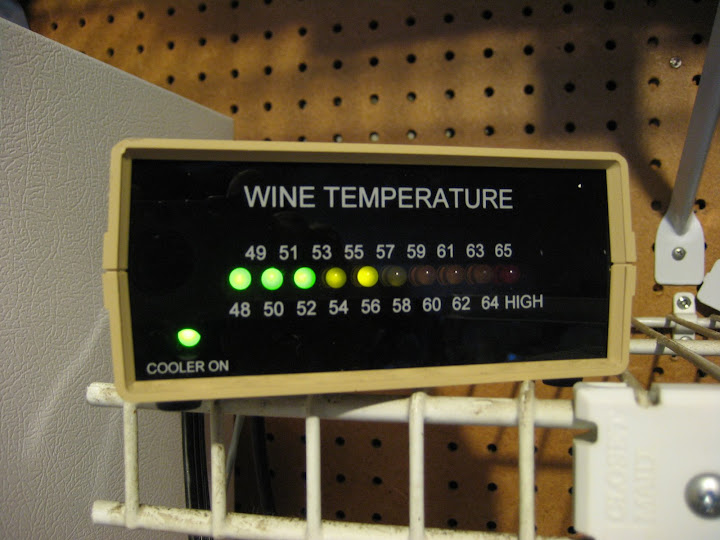 With some poking around looking for an appropriate thermostat unit, I stumbled across and older model WineStat unit on eBay, and it was mine for an uncontested $10 bid. I'm not sure how much this model was originally, but the new digital display models are $170, so I think I did ok!
After cleaning up and sterilizing the inside of the fridge (it sat for almost two years!), all I needed to complete the transformation was a way to store wine inside.
The WineStat webpage has some interesting ideas about low-cost wine racking solutions, but I chose to go with the very reconfigurable "Tinker-Toy" style racks from J.K. Adams. As it happened, Crate and Barrel had these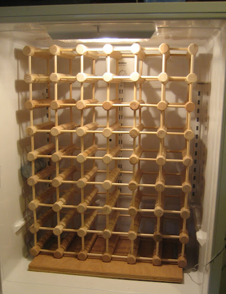 in their outlet store as "irregulars" for $19.95 for each 12-bottle kit. In this case, "irregular" meant inconsistent woodgrain color, which I was completely fine with. A "12-bottle" kit really means you get 16 "beams" and a whole pile of pins to configure however you please. With four of these kits (less one leftover beam and a few pins) I was able to build a solid 48 bottle unit that fit perfectly with room for air to circulate.
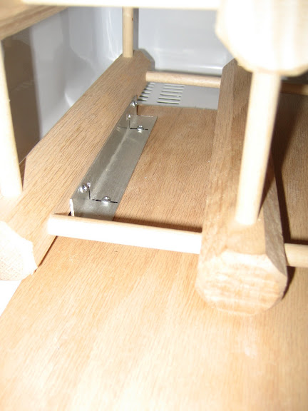 The wooden platform underneath was a leftover bit of oak cabinetry ply that flattens out the floor of the fridge box so the rack sits level. I had to cut a notch in the back left corner to clear the raised vent where cool air flows from the freezer to the fridge. A couple of quick mounting brackets made from aluminum keeps everything locked down and stable:
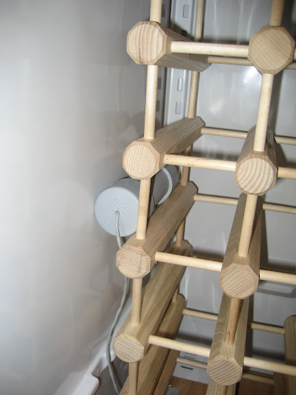 Then its just a matter of inserting the probe into the rack and plugging everything in. The probe should be centered in the box, its off to the side here while I finalized installation.
Most people don't realize that modern refrigerators depend on the thermal mass inside to help regulate the temperature. I tested the setup with several gallons of water in containers in the fridge and freezer boxes first. Once I was confident it would hold temperature, in went the wine rack, and shortly after, the wine!
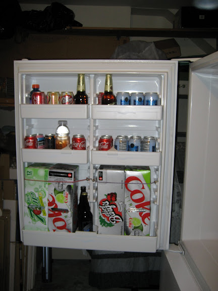 Agitation is bad for wine, so I resisted the urge to pack in more bottles using the spaces in the door. Instead, I filled this area with the soda, beer, and other beverages that would have otherwise been stored in the pantry. Its not ice-cold refreshing, but its pre-chilled which saves work for the in-house fridge when items are transferred there for consumption.
Your fridge may vary, but during my bottles-of-water testing I found that in order to keep the fridge box at a wine-friendly 55°, the freezer box ended up cycling around 30-32°. This is below freezing, but not in a zone that I feel is safe for frozen food storage.
In order to turn this into a win-win-win situation, I'm keeping the freezer box filled with gallon bottles of commercial drinking water in PET containers (with room made for freezing expansion). This constitutes part of my backup water supply in case of emergency (my wife lived through the Northridge quake and we've been on evacuation notice for wildfires here twice in the last 4 years). Having additional ice on hand will also allow me to transfer to the in-house freezer to keep frozen food safe longer if we lose power during an emergency. Lastly, the frozen mass of water helps stabilize the box temperature as the thermostat controller goes through its hysteresis, which also lets the box stay "off" longer, using less power.
The only issue left to be resolved is humidity. 60-70% would be best for keeping the corks happy, but food fridges are usually pretty dry. For now I'll probably keep a small tin of water in the box, but I plan on investigating the humidifier units people use for large cigar humidors.
All up, I've expended less than a $100 cash and a few hours time to clean up the old fridge, assemble the tinker toys, and mount and test the system. More pictures with detail photos of some items are available in the album: Low-Budget Wine Cellar.
(04/21/08)UPDATE: I've added new photos to the album. You can see that our cellar is already full. Time to have a party! Read More...
At one point we had so much wine in the house that in order to keep track, I wrote an Access database program I dubbed "Wine Collector" (in homage to my favorite DVD database product Movie Collector).
We aren't really snobs, we'll drink a big range of stuff, but some of the wine we have is pretty good, and we'd like to keep it that way. Unfortunately, commercial wine cellars (aka "wine coolers" or "wine fridges") are pretty expensive, especially if they hold any reasonable amount of wine. The smaller units are typically underpowered vanity items that only store one or two dozen bottles, and usually don't do it very efficiently. There are some exceptions of course, high quality under-counter jobbies made by reputable companies with quality refrigeration hardware, but these are nearly as expensive as the larger models of any measurable quality.
So what to do? Well, for us we did what a lot of people do, which is that we put our wine at risk. We stored it in the house, at room temperature and uncontrolled humidity. Where possible, we squirreled cases away in the tops of closets, etc., but generally, it was somewhere in the house. I don't even want to think about what this may have done to something like a 2001 El Molino Pinot Noir.
Then, I stumbled across some wine collector websites where some people had been converting old fridges to wine cellars. Either by hacking the existing thermostat, or using some sort of external controller, the unit can be setup to hold a temperature more appropriate for wine (about 54° for mixed reds/whites).
Luckily, I already had an unused fridge to start with. When we moved to our new home, we brought along our old refrigerator. The buyer of the old house didn't want it, and my wife really wanted to keep it because she liked the bottom-freezer layout. After arriving, however, we figured out that the proximity of the kitchen cabinets opposite the fridge location meant that we'd be limited to side-by-side configurations, because the sweep of the doors would interfere with the cabinet. Bummer. So that fridge sat in the garage, waiting for me to clean it up and sell it or convert it to the "beer fridge". Well, now it had a more noble (and wife approved) mission ahead of it: Wine Cellar.
 With some poking around looking for an appropriate thermostat unit, I stumbled across and older model WineStat unit on eBay, and it was mine for an uncontested $10 bid. I'm not sure how much this model was originally, but the new digital display models are $170, so I think I did ok!
After cleaning up and sterilizing the inside of the fridge (it sat for almost two years!), all I needed to complete the transformation was a way to store wine inside.
The WineStat webpage has some interesting ideas about low-cost wine racking solutions, but I chose to go with the very reconfigurable "Tinker-Toy" style racks from J.K. Adams. As it happened, Crate and Barrel had these
 in their outlet store as "irregulars" for $19.95 for each 12-bottle kit. In this case, "irregular" meant inconsistent woodgrain color, which I was completely fine with. A "12-bottle" kit really means you get 16 "beams" and a whole pile of pins to configure however you please. With four of these kits (less one leftover beam and a few pins) I was able to build a solid 48 bottle unit that fit perfectly with room for air to circulate.
 The wooden platform underneath was a leftover bit of oak cabinetry ply that flattens out the floor of the fridge box so the rack sits level. I had to cut a notch in the back left corner to clear the raised vent where cool air flows from the freezer to the fridge. A couple of quick mounting brackets made from aluminum keeps everything locked down and stable:
 Then its just a matter of inserting the probe into the rack and plugging everything in. The probe should be centered in the box, its off to the side here while I finalized installation.
Most people don't realize that modern refrigerators depend on the thermal mass inside to help regulate the temperature. I tested the setup with several gallons of water in containers in the fridge and freezer boxes first. Once I was confident it would hold temperature, in went the wine rack, and shortly after, the wine!
 Agitation is bad for wine, so I resisted the urge to pack in more bottles using the spaces in the door. Instead, I filled this area with the soda, beer, and other beverages that would have otherwise been stored in the pantry. Its not ice-cold refreshing, but its pre-chilled which saves work for the in-house fridge when items are transferred there for consumption.
Your fridge may vary, but during my bottles-of-water testing I found that in order to keep the fridge box at a wine-friendly 55°, the freezer box ended up cycling around 30-32°. This is below freezing, but not in a zone that I feel is safe for frozen food storage.
In order to turn this into a win-win-win situation, I'm keeping the freezer box filled with gallon bottles of commercial drinking water in PET containers (with room made for freezing expansion). This constitutes part of my backup water supply in case of emergency (my wife lived through the Northridge quake and we've been on evacuation notice for wildfires here twice in the last 4 years). Having additional ice on hand will also allow me to transfer to the in-house freezer to keep frozen food safe longer if we lose power during an emergency. Lastly, the frozen mass of water helps stabilize the box temperature as the thermostat controller goes through its hysteresis, which also lets the box stay "off" longer, using less power.
The only issue left to be resolved is humidity. 60-70% would be best for keeping the corks happy, but food fridges are usually pretty dry. For now I'll probably keep a small tin of water in the box, but I plan on investigating the humidifier units people use for large cigar humidors.
(04/21/08)UPDATE: I've added new photos to the album. You can see that our cellar is already full. Time to have a party! Read More...
Saturday, December 29, 2007
Simple machines for building complex machines...
So, the holidays are past, and Merry Christmas to me, I'm now the proud owner of a Harbor Freight metal cutting bandsaw. This is a tool I've wanted for a long time, and was finally able to rationalize purchasing after a) it went on sale, and b) I agreed to coach the neighbor's son in the Robot Ramble competition for the Science Olympiad 2008.
We'll be re-using a lot of the components from some of my old battle-robots, like the motors from Centrifugal Enforcer, the batteries and ESCs from a pneumatic flipper-bot I built for Steel Conflict (but never did a build report for), and a few other gear motors, etc. I've got lying around in my stores. That said, there will be some fabrication, namely a new chassis, a lifting arm, and a gripping mechanism, all of which will require cut aluminum and steel.
I purchased the 130lbs+ beastie from my local HF warehouse, and got help from their staff loading it into the Subaru. Unloading was facilitated by a combination of gravity, a skateboard, and enough muscle power to nudge things in the right direction.
Assembly, however was going to be a different story. Step 4 in the assembly process reads "With a second person and appropriate lifting apparatus, set the saw base onto the saw stand and affix with hex bolts..." etc., etc.
 Basically, the operation means setting a massive hunk of cast iron, motor, and steel, something like 95% of the weight of the tool, on top of the stamped metal "legs" that form the base.
This is one of those engineering arrangements that's strong once you have everything bolted together, but isn't conducive to supporting one corner of the machine while you lift the other bits into place. This was looking sketchy to say the least.
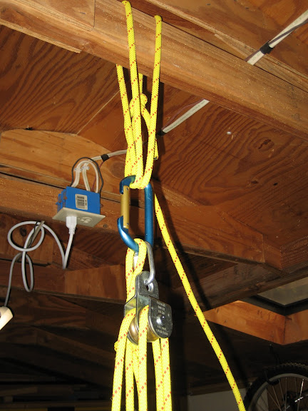
I didn't have access to a second person, but I could certainly arrange for an appropriate lifting apparatus, so after 20 or 30 minutes of scrounging in the garage and piecing things together, I'd managed some poly rope, carabiners, and pulleys. I lashed these to the joists of my workshed.
 Mix in some nylon straps from the completely over-engineered hoist I'd built for the hardtop of the Miata @ my old house....
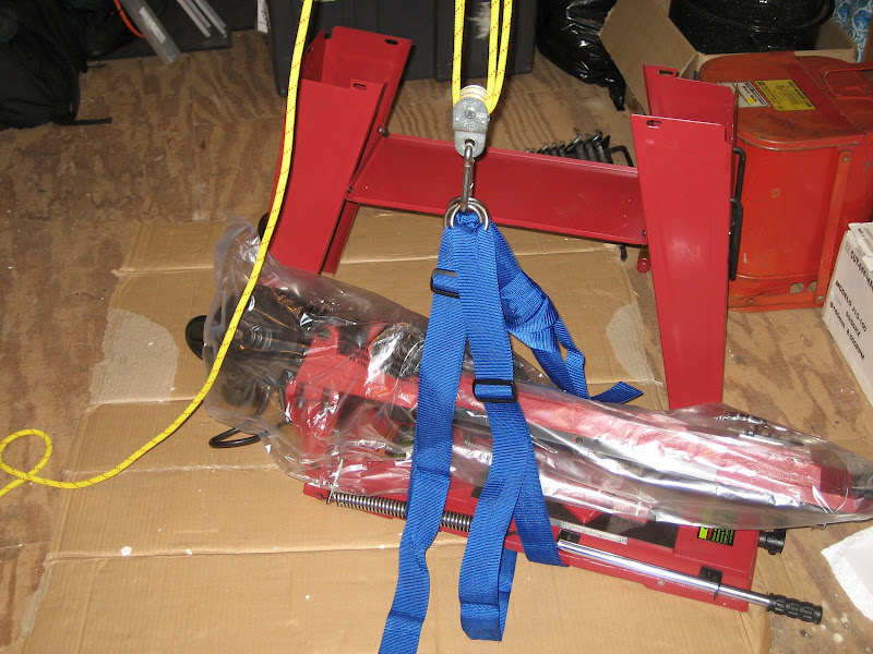
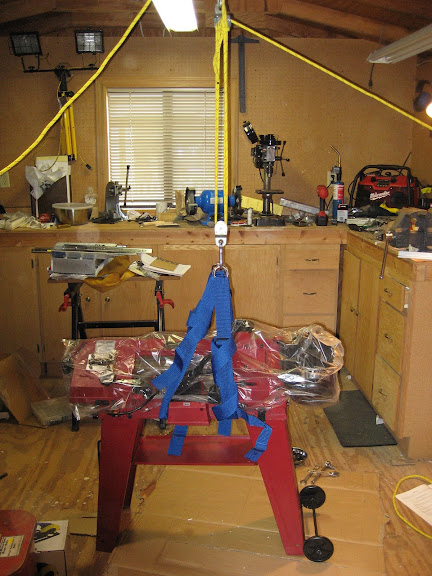
Adjusting the length of the nylon straps allowed me to compensate for the relatively ass-heavy nature of the tool. Lifting a few inches to test for balance then setting it down for adjustments took just a few tries. Eventually I was able to lift it to a working height and bring the base underneath for attachment.
 After that is when the typical Harbor Freight adventure began, as the instructions were apparently for a different version of the tool. The stand that was supposed to bolt to the outside of the machine bed was clearly designed to go inside of the bed. The bolts I was instructed to fasten to "threaded holes" in the machine bed were of a barely-adequate length and the holes were not threaded (nuts supplied instead). Due to the wonder of Chinese tolerance keeping, I needed to substitute a bolt of my own as one of theirs was too short. Oh, and then there was the crusted cosmoline. A judicious application of white gas, WD-40, and an elbow-grease powered scraper cleared the beds and mating surfaces of hardened rust preventative. The best part, though, was all of the pulley-related parts I had to remove in order to install the pulley cover. (Pulleys go on last, yet came pre-installed).
In the end, though, with some care adjusting the clamps and feed adjuster, I have a functioning band saw that cuts my extruded aluminum channel very cleanly and squarely. I'll test on steel as soon as I get the chance.
Read More...
We'll be re-using a lot of the components from some of my old battle-robots, like the motors from Centrifugal Enforcer, the batteries and ESCs from a pneumatic flipper-bot I built for Steel Conflict (but never did a build report for), and a few other gear motors, etc. I've got lying around in my stores. That said, there will be some fabrication, namely a new chassis, a lifting arm, and a gripping mechanism, all of which will require cut aluminum and steel.
I purchased the 130lbs+ beastie from my local HF warehouse, and got help from their staff loading it into the Subaru. Unloading was facilitated by a combination of gravity, a skateboard, and enough muscle power to nudge things in the right direction.
Assembly, however was going to be a different story. Step 4 in the assembly process reads "With a second person and appropriate lifting apparatus, set the saw base onto the saw stand and affix with hex bolts..." etc., etc.
 Basically, the operation means setting a massive hunk of cast iron, motor, and steel, something like 95% of the weight of the tool, on top of the stamped metal "legs" that form the base.
This is one of those engineering arrangements that's strong once you have everything bolted together, but isn't conducive to supporting one corner of the machine while you lift the other bits into place. This was looking sketchy to say the least.
I didn't have access to a second person, but I could certainly arrange for an appropriate lifting apparatus, so after 20 or 30 minutes of scrounging in the garage and piecing things together, I'd managed some poly rope, carabiners, and pulleys. I lashed these to the joists of my workshed.
 Mix in some nylon straps from the completely over-engineered hoist I'd built for the hardtop of the Miata @ my old house....
Adjusting the length of the nylon straps allowed me to compensate for the relatively ass-heavy nature of the tool. Lifting a few inches to test for balance then setting it down for adjustments took just a few tries. Eventually I was able to lift it to a working height and bring the base underneath for attachment.
 After that is when the typical Harbor Freight adventure began, as the instructions were apparently for a different version of the tool. The stand that was supposed to bolt to the outside of the machine bed was clearly designed to go inside of the bed. The bolts I was instructed to fasten to "threaded holes" in the machine bed were of a barely-adequate length and the holes were not threaded (nuts supplied instead). Due to the wonder of Chinese tolerance keeping, I needed to substitute a bolt of my own as one of theirs was too short. Oh, and then there was the crusted cosmoline. A judicious application of white gas, WD-40, and an elbow-grease powered scraper cleared the beds and mating surfaces of hardened rust preventative. The best part, though, was all of the pulley-related parts I had to remove in order to install the pulley cover. (Pulleys go on last, yet came pre-installed).
In the end, though, with some care adjusting the clamps and feed adjuster, I have a functioning band saw that cuts my extruded aluminum channel very cleanly and squarely. I'll test on steel as soon as I get the chance.
Read More...
Saturday, February 17, 2007
WBC Sidebar: LNT and Ultralight Backpacking
A couple of friends who know I'm an ex-boyscout and generally sort-of-experienced person have asked why I'm taking a course like the WBC. My answer is that after 15 years off from serious backpacking, a lot of things have changed. Gear is lighter and better, and the philosophy behind the "low impact" techniques I learned in Scouting have morphed into the "Leave No Trace" philosophy. The biggest change I can point to is that its now common practice to pack out used TP, whereas it used to be buried. On our Snow Camp trip, where the potential impact is much higher due to large numbers of students in a relatively small area, we'll even be packing out our human waste.
Another big innovation is the philosophy of "Ultralight Backpacking". In the old days 35, 40, or 50+ lbs was a normal packload for even a short trip. Using the old "25% rule", someone my size would expect a load of 50lbs. However, advancements in gear technology and a commitment by some to "do more with less" has brought about a revolution to drive down the weight of packs. Some ultralighters have a base pack weight (gear minus food, water, and fuel) down below 10 lbs! There are some interesting synergies, like a reduced pack weight lets you use lighter boots (or even trail runners) rather than the heavy 3/4-shank all-leather monsters I grew up with. This amplifies the effect of a lighter pack, allowing easier (or more) miles underfoot.
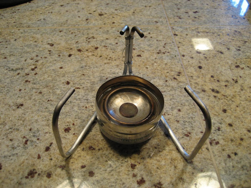 One of the things I've been experimenting with since first learning about Ultralight backpacking, is Alcohol stoves. In particular, super-lightweight stoves made from aluminum cans. The advantages are obvious upon inspection: The stoves are simple (no moving parts), compact (made from cut-down beer cans), and weigh a fraction of the weight of even the lightweight backpacking stoves of commercial manufacture. Compared to my old MSR Whisperlite, the difference is amazing.
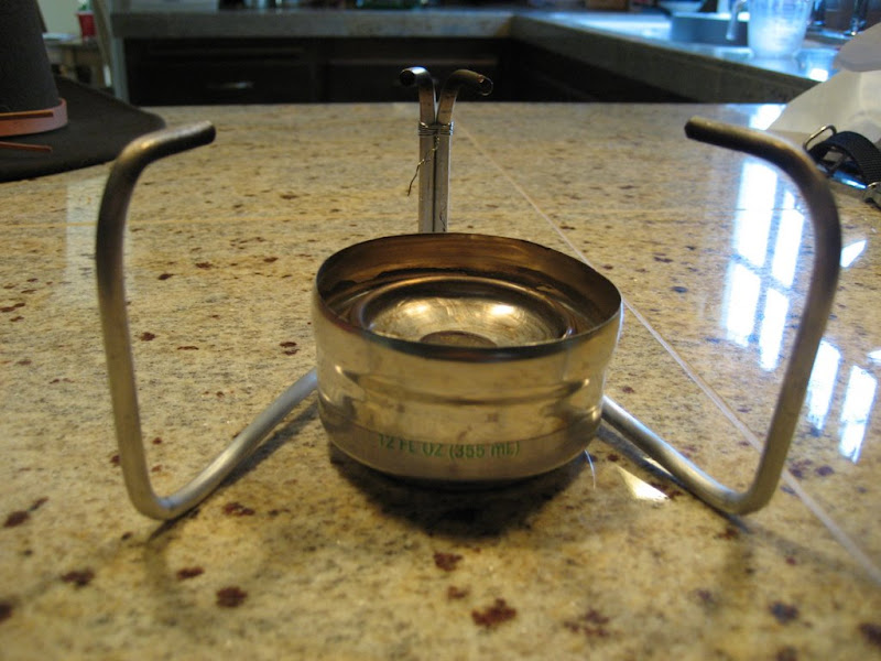 I used Mark Jurey's Penny Stove example when creating my first stove. I'm sure I'll try another at some point, but for now I'm really happy with the results. This particular stove uses a pair of the Heineken "Keg Cans" for the burner and fuel cups, and a soda can (diet 7-up for those keeping score) for the base/lid. And of course, the namesake penny as the regulator. The stove actually develops a small amount of pressure as the denatured alcohol fuel is vaporized in the cup. The weight of the penny over the central holes is enough to keep the pressure at a good level but allow venting (and an extra central jet) when the pressure gets too high. A "simmer ring" (see bottom of picture below) redirects the jets and slows the evaporation of the fuel, allowing a longer/cooler burn time for simmering food. The design genius in its simplicity. I had some trouble with sealing the construction of mine so I went ahead and "caulked" the cups together with JB weld, but most folks get a pressure-tight fit from interference alone. Impressive!
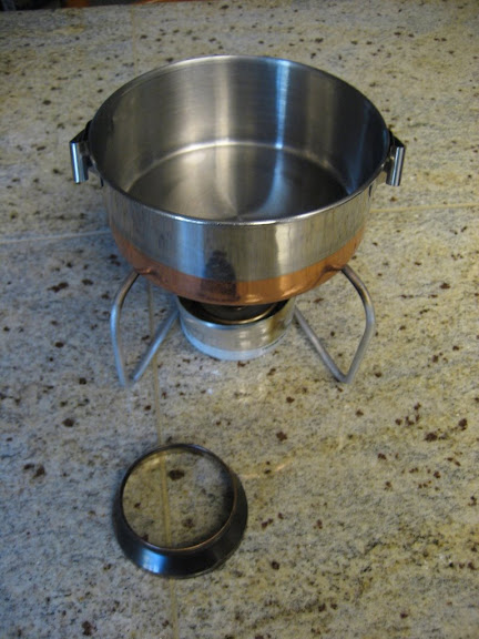 I've also upgraded to a 1.3L Snow Peak titanium cookpot to replace the old stainless pot seen here. Its lighter, despite the greater capacity, and should be a bit more efficient too since its black rather than the reflective exterior. The important metric of this experiment is the weight of the whole cooking "system", as there's more to consider than just the stove. The one disadvantage to alcohol over white gas or pressurized liquid fuel canisters is that alcohol burns at a lower temperature and has a lower overall energy density, meaning that you have to carry more fuel per meal. On the other hand, the denatured alcohol fuel can be carried in a lightweight plastic water bottle or other such vessel (I use a flat-square soap bottle that fits my cookpot well), while white gas has to be carried in a spun aluminum bottle with a gasket and pressurized fuels have their own disposable metal canisters. The massive weight savings of the stove itself, along with the fuel bottles and ancillary bits means that I'd have to be going on a pretty long trip (5+ days?) before the fuel weight difference would overtake and make a white gas stove a lighter alternative.
One of the things I was using the Car-Camp outing for was to try some new gear and new techniques. It was a good chance to try some stuff without having a failure be totally catastrophic. A new lunch system was tried with great success, and I had mixed feelings about the new sleeping bag and tent I'd rented from REI. All of these experiences get fed-back into my gear for the next outing. I'll use the next outing to evaluate my new cooking system in the same way, although backyard tests have shown that the time-to-boil for two cups of water is only about a minute longer than with white gas. Read More...
Thursday, February 01, 2007
Hack of the Day: Mini-Hacks!
I stumbled across a pair of nice little tips today, and I love doing my Hack of the Day topics, so here's a tidy collection of random tips that jut might hack your life for the better:
I love Firefox. I love tabbed browsing. I love one-click closing of tabs. But sometimes, due to my own fumble-fingeredness, I miss-click or over-click. Problem solved:
Firefox Tip: Reopen the last closed tab with Ctrl+Shift+T - Lifehacker
Secondly, my memory is pretty good, and most folks loathe playing trivia type games with me, since my noggin is full to leaking with ephemera and minutia. But for the life of me, for inexplicable reasons, I have problems remembering something that others find basic: How many days in the month of March? Or April? Well Lifehacker rescues me again with their MacGyver Tip today:
Use your knuckles to remember each month's days.
I love it, especially because its physical, usually once I've pantomimed or otherwise made handsigns for a memory aid a couple of times, it sticks with me. Stuff like the Left Hand Rule for current and magnetic flux tends to stick pretty well. Here's hoping the days in a month do too! Read More...
Thursday, January 25, 2007
Hack of the Day: Magnetic Spice Rack
Came across this the other day, and it reminded me that I never blogged on my own solution to the "problem" of kitchen spice management.
My Aim Is True: DIY: Magnetic Spice Rack
When it came time to setup the kitchen in our new house, I wanted my spices to be better organized and more accessable than they'd been at the old place. Being a die hard Alton Brown and Good Eats fan, it was a natural that I chose an in-cabinet solution, to offer better visability to my collection (versus the 5-rows deep of spice containers in a high cabinet that many folks have). It also keeps the spices out of the sun, away from damaging heat and most importantly, doesn't burn counter space.
Here's my solution, which is similarly magnetic:

I went magnetic because we found a great deal on a spice kit similar to this one on clearance at Sears. The shakers already had magnets on the back and have two "cutouts" around the rim that allow either light or heavy spice shaking without having to remove the lids. The plates are Ikea "BAR" message boards, a whopping $0.99 each. Note that I've combined two different kits worth of spice shakers here... I have a lot of spices.
I like the inventiveness of Amber's project, but the aforementioned heat and light are big issues when it comes to the useful life of spices. If you're starting with plain watchmakers cases like Amber did, you could either go magnetic or make like Alton Brown himself and just use self-adhesive Velcro strips. However I've seen lots of knock-offs of the magnetic tins at places like Lowes, Sears, etc. and they're a lot cheaper than the Amazon example, so you might actually save money not doing everything from scratch.
EDIT: OK, a tipster in another thread pointed to these at Sciplus, which is pretty damn cheap for a similar solution. In this case, gluing your own magnets or velcro will almost certainly be cheaper. Man, I haven't been to Sciplus in months. Need to start checking back there on a regular basis.
Read More...
Tuesday, January 23, 2007
Hack of the Day: Microwave your Kitchen Sponge
Like a lot of people, we use kitchen sponges at home for washing pots, scrubbing the stuff stuck on plates before the dishwasher, etc. And like a lot of people, we worry about what's actually living in the cells of those little cellulose critter catchers...
We change sponges regularly out of these concerns, but the reality is that the sponges are probably just as nasty on Day 2 as they are on the day we throw them out. Thus, I love the simplicity (and the chance to prolong sponge life and reduce waste) of this idea from LiveScience:
LiveScience.com - Study: Microwaves Kill Kitchen Germs
OK, the title of the article is a little misleading, its not microwaves that do the killing, per se. The reality seems to be that the heat generated by microwaving a wet kitchen sponge is enough to sterilize it. They recommend 4 minutes to ensure death to even the nastiest, hardest to kill spores. I can say that based on my experience with modern microwaves, 4 minutes on "High" for the amount of water in a normal kitchen sponge is definitely enough to superheat the water (i.e. raise it beyond the normal boiling temperature), which will certainly get it well into critter killing temperatures.
WARNING: Be extremely careful removing the newly nuked sponge from your 'wave. It will be hot, Hot, Hot!
NEW WARNING: Apparently some people didn't twig to the fact that its hot water that does the sanitizing and there were a rash of fires and problems with people microwaving dry sponges. YOU MUST WET THE SPONGE!
Personally, I plan to use a small microwave safe dish for this, since then I can nuke the sponge after the morning breakfast cleanup, set it on the counter, and let it cool back to sub-plasma temperatures while I head to work.
Read More...
Tuesday, August 09, 2005
Hack of the Day: Altoids iPod Armor Redux
Needed a break from reading specs at work today, decided to update my implementation of my Altoids-tin-turned-iPod-case.
Originally, I had trimmed a section of the original vacuum formed plastic Shuffle packaging to fit the Altoids tin. It had the Shuffle-shaped recess to hold the player and a bit of "flange" sticking out to keep this section from moving around too much. There were two major negatives of this implementation:
Originally, I had trimmed a section of the original vacuum formed plastic Shuffle packaging to fit the Altoids tin. It had the Shuffle-shaped recess to hold the player and a bit of "flange" sticking out to keep this section from moving around too much. There were two major negatives of this implementation:
- The extra plastic that held things in place left very little room for the earbuds. Unless I was very careful about coiling the cord and put the buds in place just right, then the case wouldn't close reliably. This was dumb because there was plenty of wasted volume under this bit of plastic.
- Listening to the shuffle meant removing it from the tin and either clipping it to the lanyard (which I don't always wear because it also has my RFID work badge), or leaving the shuffle to bang around in my pocket or bag.
- First I needed to solve the problem of too-little room for the earbuds. I re-trimmed the fitted rectangular recess so that it was mostly just the space for the Shuffle, with a very short flange on the topside to space the Shuffle away from the edge of the tin just slightly. This made tons of room for the earbuds, but the fitted plastic is free to move around the tin which would be very inconvenient. Note that since I planned to be able to plug the earbuds in through the case, I trimmed the fitted-rectangle so that it was slightly off center, placing the jack as close to one edge of the tin as possible.
- Next, I scrounged a new piece of thin vacuum-formed
 plastic, with a flat section large enough to cover the bottom of the Altoids tin. I think mine was from an OEM hard drive blister pack or something similar. Laying this over the top of the tin, I marked the corners and trimmed it to fit snugly into the tin. You can still see the markings in the photo, which is helpful to see the shape, since its clear plastic on a light colored background. This will serve as a "baseplate" which will keep things from moving around inside the tin.
 - I placed the new baseplate into the tin, and then the fitted rectangle on top of it. I used three small drops of superglue to attach them to each other, but not to the tin. (Its helpful to be able to remove this assembly from the tin, either to replace the tin if it gets damaged, or for convenient marking if you're proceeding with Step 4.)
- OK, that takes care of the
 earbud problem, now there is plenty of room for the buds, but the Shuffle-shaped plastic is held firmly in place inside the tin. If you don't care if you are able to listen to the Shuffle while it's in the tin, you can stop now. Otherwise, continue: I removed the plastic assembly from the tin, and inserted the Shuffle into the recess, then marked the location of the earbud jack with a fine-tipped marker.
 - Remove the Shuffle and make a hole 3/16" to 1/4" in diameter in the plastic. Note that in order for the earbuds to plug all the way in, the hole needs to be as big as the wide portion of the plug, not just the 1/8" width of the tip-ring-sleeve portion. To make the hole, do whatever you feel is safe that will make a clean hole. Don't stab yourself in the hand trying to poke through with a knife. Easiest is to make a small hole and file it out, or heat a 1/4" piece of rod to red-hot and just melt a hole...
- After confirming that the hole is in the right place, and big enough for the jack, temporarily replace the plastic assembly in the tin and use it as a template for marking for a hole in the
 side of the tin. The easiest thing for me was to use a sharp scribe to just barely mark the center of the hole from the inside, then centerpunch and drill the hole from the outside,(after removing the plastic, of course). If you have a tapered reamer, I'd drill a small pilot hole and then ream the hole to size, for safety. If you're careful, you should be able to drill it to size, just be careful of the drill bit grabbing into the thin sheetmetal as you punch through the tin. Clean up the hole, if needed, and reinsert the plastic assembly for the final time. Voila', you can now store your iPod Shuffle and earbuds in armored security or have the option of listening to the Shuffle while its in the tin.
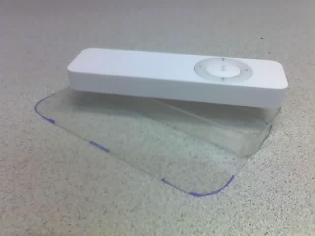
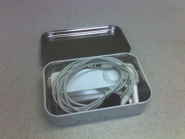
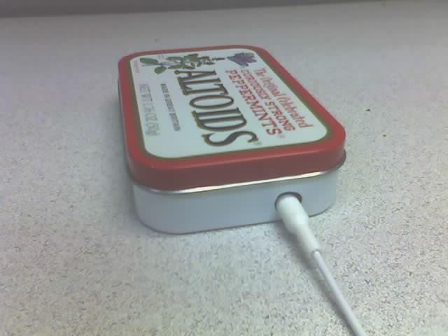
- One Altoids tin - If you're like me, you've got 20 in a drawer somewhere (Free), if not: $2.00 or so...
- The original vacuum-formed blister pack from your iPod Shuffle package. (Free). If you didn't keep this, you'll need to try one of the other mods listed above.
- A flat piece of thin plastic large enough to fit the bottom of the Altoids tin. There might be a large enough piece from the original packaging for this purpose, I don't remember. Just about anything will work here... (Free)
- 3 Drops of Superglue, borrowed from a tube at work. (Free, or ~$1 for more than you're ever need.)
Subscribe to:
Posts (Atom)

